Toyota 4 Wire O2 Sensor Wiring Diagram Esquilo.io
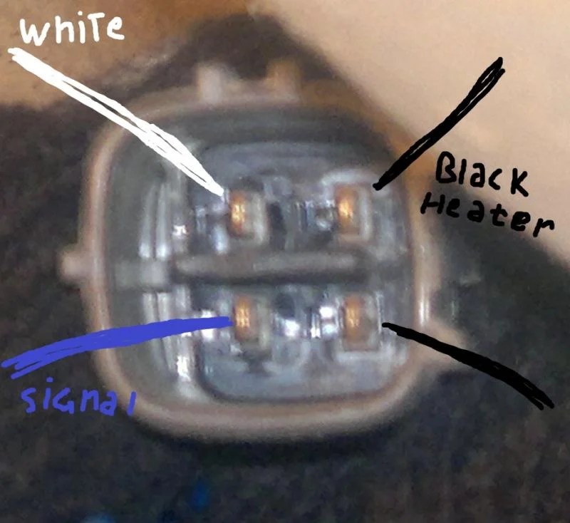
As you're probably already aware, the front O2 sensor has 4 wires sticking out of its connector. To test the O2 sensor #1's heater, we need to know which wire supplies it with power. We also need to know which terminals, of the connector of the O2 sensor itself, are part of the heater element circuit inside the O2 sensor.

Corolla P0138 trouble code — Ricks Free Auto Repair Advice Ricks Free
Watch on Troubleshooting 4 Wire O2 Sensor Wiring Issues Step 1: Recognizing Common O2 Sensor Wiring Issues Incorrect wiring connections Wires that are damaged or frayed Corrosion or rust affecting wires or connectors A malfunctioning or defective O2 sensor Step 2: Indications of O2 Sensor Wiring Problems Reduced fuel efficiency

O2 Sensor Wiring Diagram
Find the deal you deserve on eBay. Discover discounts from sellers across the globe. We've got your back with eBay money-back guarantee. Enjoy O2 sensors you can trust.
Jeep Oxygen Sensor Wiring Diagram
The 4-wire oxygen sensor diagram provides essential information about the wiring and color coding used in this type of sensor. Understanding these details is crucial for accurately interpreting the diagram and properly installing or troubleshooting the oxygen sensor.

Understanding 4 Wire O2 Sensor Wiring Diagram Basics Wiring Diagram
The 4 wire O2 sensor wiring diagram Nissan is a wiring diagram that explains how the oxygen sensor is wired into the engine. The diagram shows the connections between the oxygen sensor, the engine's computer, and the power source. It also shows the color code of the wires that connect the components.
Chevy 4 Wire O2 Sensor Wiring Diagram
Online manuals and video tutorials only available via Haynes direct. Search hundreds of online and print manuals and get expert repair guidance from Haynes.

Hyundai O2 Sensor Wiring Diagram
1. Long usage Long usage happens to be one of the most common reasons that cause the O2 sensor to fail. The oxygen sensor's lifespan should be 3 to 5 years or 60,000 to 90,000 miles. Just like every other component in the vehicle wears out, that's how the oxygen sensor also wears out over time.

Wiring Diagram For O2 Sensor Wiring Diagram Schemas
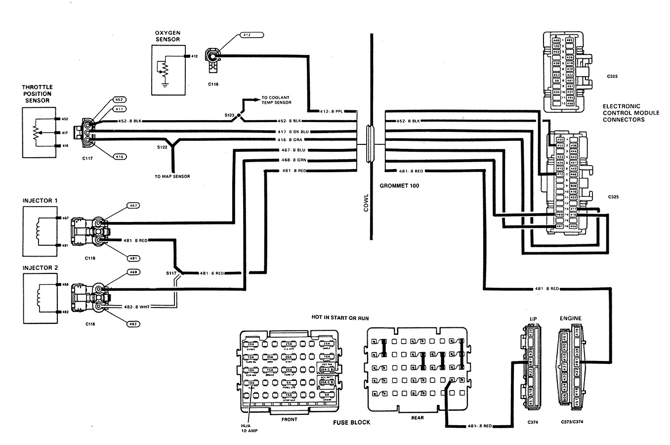
The oxygen sensor is located in the exhaust system. An oxygen sensor wiring schematic is a drawing that shows how the oxygen sensor is connected to the vehicle's electrical system. The diagram will show the location of the oxygen sensor, the type of sensor, and the color of the wires.

4 Wire O2 Sensor Wiring Diagram Printable Form, Templates and Letter
1 Answer Sorted by: 16 No, you don't have to rely on wire colors to figure out what's what. With nothing more than a decent multimeter and premix flame (blowtorch or gas stove), a two-test sequence can reveal the identity of each wire, assuming the O2 sensor is fully-functional: Determine the heater wires This should be done first.
Bosch 4 Wire O2 Sensor Wiring Diagram Fab Base
Common symbols used in O2 sensor wiring diagrams include arrows and lines that indicate the power and polarity of a particular wire. Additionally, common letterings such as "L" and "M" indicate the power and direction of a current, as well as naming specific wires with names like "12V" and "GND", respectively.

42 4 wire o2 sensor wiring diagram
The wiring diagram in Figure 6 is typical of what you may see in service information, please note that there are six wires shown in the diagram. There will be a total of six wires on the ECM side of the circuit but only five wires on the actual Bosch wide range oxygen sensor. If you look closely at the Bosch wiring diagram above and follow the trim resistor circuit, it will offer some insight.
Tool Briefing Can Bus Communication Failure 2 Wire Speed Sensor
The diagram shows black is ground, the red/yellow as the power/fuse wire, the white as ECM "Signal to computer" wire and orange/black just has the abbreviation O2HFR. 2)The new O2 has 2 browns, a purple and tan wire. 3)The instructions it came with say connect blue to Signal wire, two blacks to to either heater wires.

Bosch 4 Wire O2 Sensor Wiring Diagram Database
To test a 4-wire oxygen sensor's input voltage: Disconnect its plug, turn the ignition on (without starting the vehicle), set the multimeter to DC volts, and connect its black probe to the battery's negative terminal and its red probe to the plug's heater wire. The voltage should be above 12 volts.
Chevy Cruze O2 Sensor Wiring Diagram
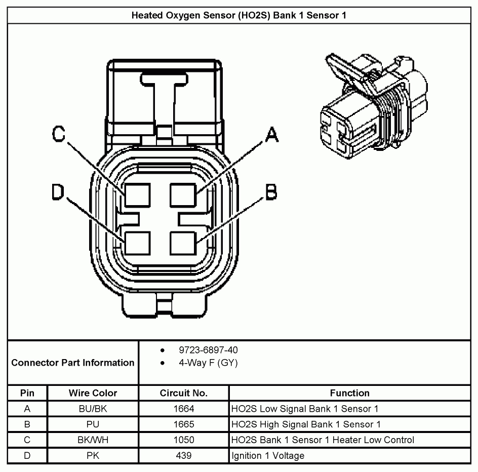
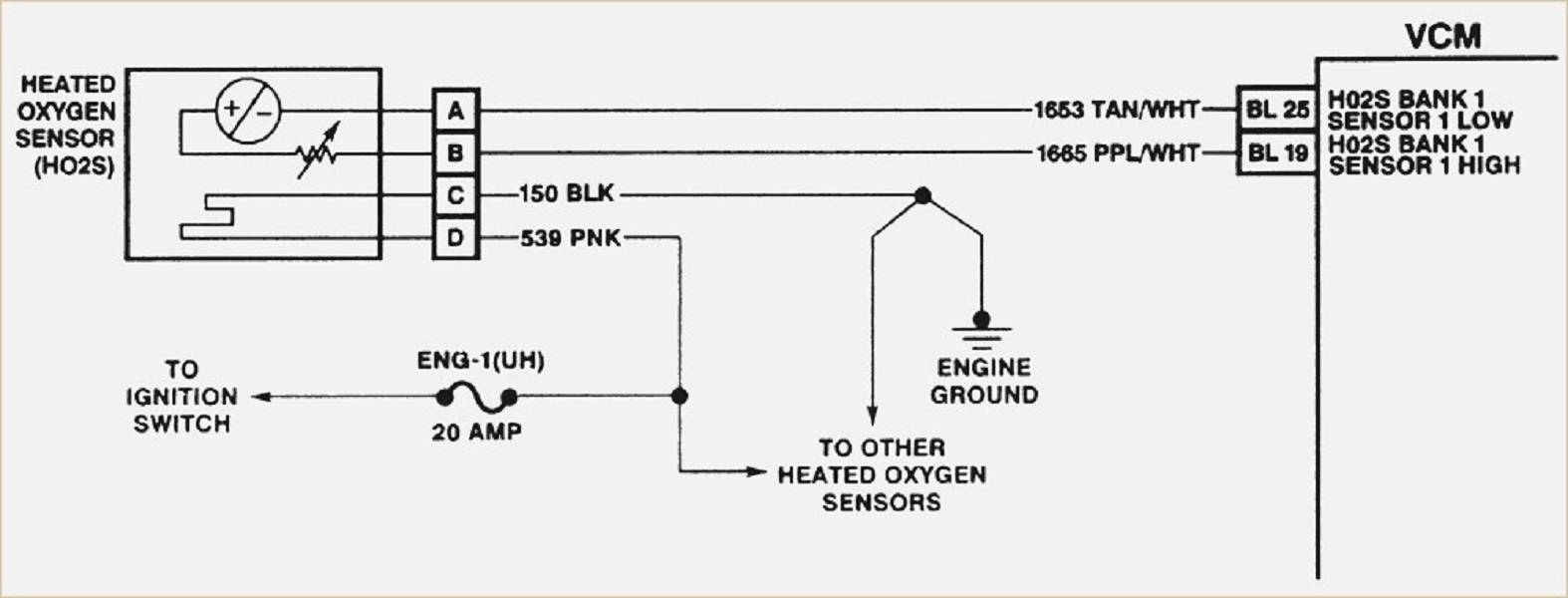
The wiring diagram for a 4 wire oxygen sensor includes four wires: two for the oxygen sensor signal and two for the sensor's heater circuit. The oxygen sensor signal wires are responsible for transmitting the voltage signal produced by the sensor to the engine control module (ECM).

4 Wire O2 Sensor Wiring Diagram Nissan
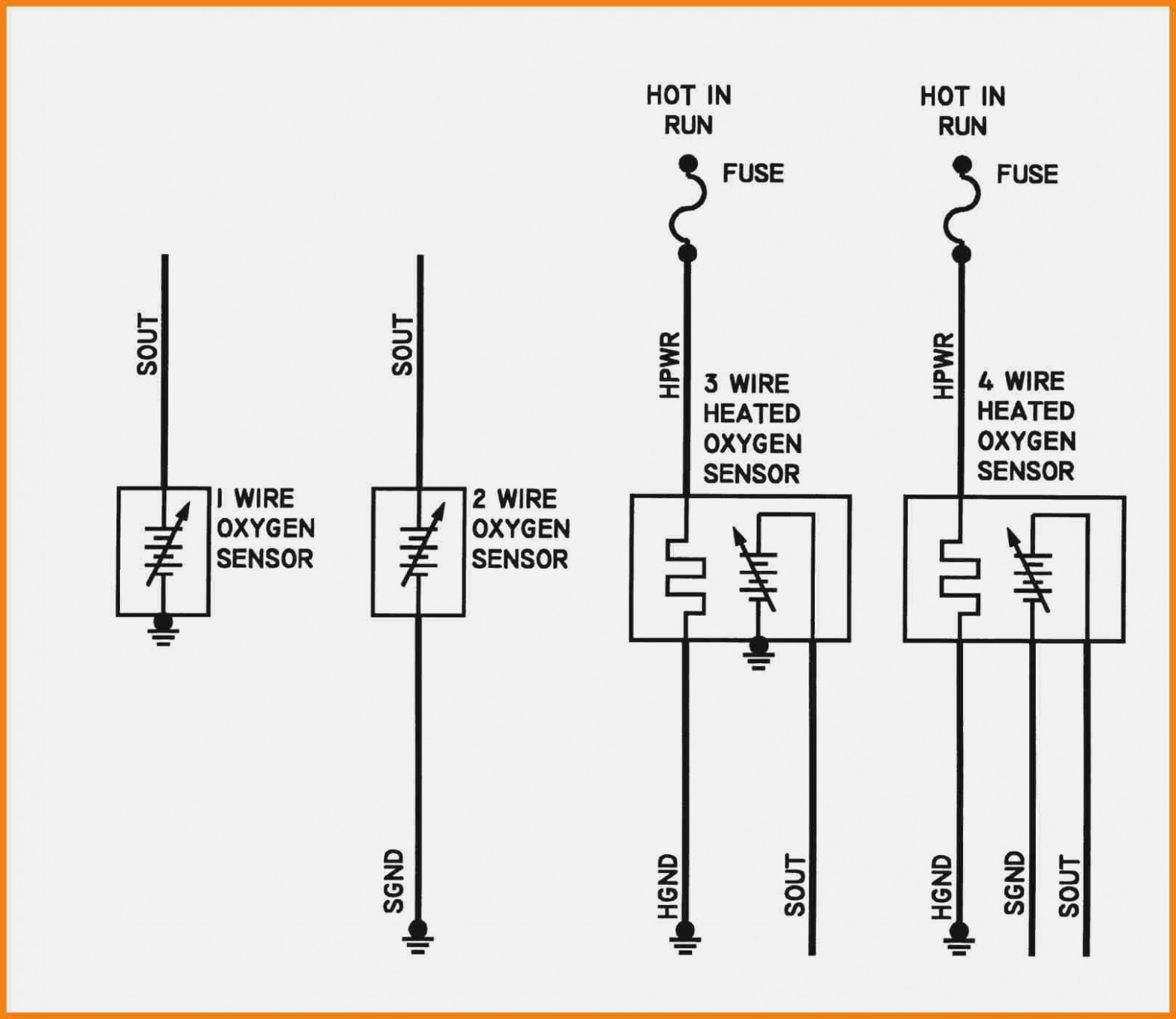
A 4-wire O2 (lambda) sensor, as the name implies, has four wires that connect to the vehicle's harness and through it, the ECU. The four wires are named after the task they perform: Heater Element Ground Heater Element Power O2 Sensor Ground O2 Sensor Signal
bosch 4 wire o2 sensor wiring diagram RihaniNurlita
The wiring diagram will show the correct way to connect the sensor wires, including the ground, signal, and heater wires (if applicable). Following the wiring diagram carefully is essential to ensure that the heated oxygen sensor is properly installed and functioning.